MicroCAN-FD
One of my current projects: a compact 'micro' dual-channel CAN/CAN FD device, with supporting Arduino board support package, firmware and libraries.
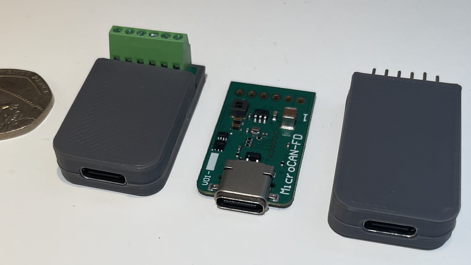
MicroCAN-FD is something I’ve wanted to develop for a very long time. I’ve recently had a reason and the time to dedicate to it, and I wish I had started this years ago; it’s already proving useful and I’m already using it as a CAN Bus analysis tool and translator device.
It is a very small dual-channel CAN/CAN FD board for translation, gateways, filtering, blocking, emulation, message injection and vehicle-system experimentation.
Originally this was purely for my own projects, especially engine conversions and vehicle electronics work. But it will also have its use in any CAN Bus application, such as agriculture, plant equipment and industrial automation. If there is genuine interest, it may turn into a small production run later, but I am not presenting it as a finished commercial product yet.
The project pulls together a lot of work: the schematic and board design, enclosure design, Arduino board support package development, CAN driver development, Arduino (c++) libraries, web app development and understanding the DBC format. All of the firmware is open source, but I am not presenting MicroCAN-FD itself as a fully open-source product at this stage.
What is it
The board is designed to be cheap enough to leave permanently in a vehicle and small enough to fit inside an ECU, instrument cluster or other module. It’s powered by USB-C for debugging and development, or through the VIN terminal which accepts 8-36V for permanent installation, both can be connected at the same time and the HW will automatically switch to VIN when connected. The Power, Ground and CAN bus connections are all on the same side making wiring easy, and the connector is a standard 2.54mm (0.1”) pitch so it can accept screw terminals, header pins, direct wiring or Molex KK-254 style locking connectors on the same footprint.
The hardware has the following specs, so it is more than enough for any dual CAN Bus application, even at full FD speeds:
- Microchip ATSAME51 MCU with the following specs:
- 120MHz ARM Cortex M4
- Floating Point Unit, DMA, Crypto Engine, Memory Protection Unit
- Up to 1024KB flash and 256KB SRAM
- Automotive Qualified
- Dual CAN / CAN FD channels, 2.0 A/B up to 1 Mbps and FD up to 10 Mbps, with each CAN controller containing the following:
- HW Filters, 2x 64 element receive FIFOs, 64 receive buffers
- Error logging, Loopback modes, HW interrupts etc.
- Transmit FIFO, 32 transmit buffers, Event FIFO
- 8-36 V input so it can work in cars, vans and HGV/trucks. This was by far the hardest part of keeping it small, it could be a lot smaller if we only wanted to support 12V or even 5V.
- Full speed USB 2.0 and USB-C connector.
- On board 120ohm termination with solder jumpers.
- Screw terminals, header pins, direct wiring or Molex KK-254 style locking connectors on the same footprint.
- Optional plastic enclosure for mounting inside ECUs, instrument clusters and modules without shorting anything
- On board 32.768 kHz crystal for timekeeping, such as CAN Bus timestamps etc.
As described above this is designed as a device that can be left in a vehicle, used for development, and cheap enough to keep a handful in stock to have on hand when you need it. Rather than being a dedicated high-speed CAN analyser, MicroCAN-FD is designed as a translator, gateway, emulator and development platform. It will comfortably analyse and stream two channels of CAN 2.0 traffic and the vast majority of CAN FD networks you’ll encounter in the real world, but if your goal is capturing two fully saturated 10 Mbps CAN FD buses simultaneously, you’ll need dedicated high-end analysis hardware. Think of this as a translator, emulator, gateway, or mod chip, capable of any CAN Bus application involving two channels of up to 10 Mbps each. The USB port is for programming, debugging, development and reverse engineering/sniffing. That being said, the web app and library is written in such as way that when the USB stream is at its limit, each CAN bus message gets a fair shot at appearing in the analyser window without crashing. I regularly use it to sniff and reverse engineer CAN FD and it works very well; I am already using it as my main CAN bus analysis tool, it has largely replaced my Kvaser Leaf, and it’s always done everything I’ve wanted of it.
Why I built it
I wanted a device that is low-cost enough to keep a few on hand at all times:
- That I could permanently install inside a vehicle
- Quickly write firmware for using Arduino
- Reuse across projects without reinventing everything each time
- Use as an analysis tool and for debugging without using a dedicated high-cost analysis tool
There are plenty of dedicated emulators on the market, AdBlue, Steering Lock (ESL), Electronic Ignition, Immobilisers etc and a few dedicated controllers for instrument clusters or electronic power steering (EPS), but these are all typically hard coded with no option to reconfigure them after purchase. There are also plenty of high-cost analysis tools, costing several hundred £/$/€.
As far as I know there is nothing super small, with two CAN Bus channels that can be programmed to do whatever you want it to do, hence I made this.
What does it do
The sort of jobs I have in mind are:
- Engine swaps that need CAN translation between incompatible modules.
- Instrument cluster conversions.
- KM to miles conversion on imported vehicles.
- Blocking or translating unwanted warning messages.
- ABS, EPS and other module removal or modification.
- Emulating modules such as immobilisers, AdBlue, NOx sensors or other missing devices.
- Translating data between ECUs that were never meant to talk to each other.
- Injecting or overriding messages for testing and development.
- Reverse engineering, analysis, debugging and sniffing tool.
In simple terms, it is for the jobs where you need to manipulate, translate or emulate CAN Bus, or use it to debug, analyse and sniff out CAN Bus data.
Videos and examples
These clips show some early MicroCAN-FD development, these are all controlling a Mazda RX-8 instrument cluster as I have fully reverse engineered the CAN Bus protocol in an earlier project.
They are development videos taken on by phone, rather than polished product videos.
The above video shows the device in full control of a RX-8 instrument cluster, you can see it sweeping the RPM gauge and speedo and at the same time it loops through each warning light, with the oil pressure and coolant temp gauges also controlled.
The above video shows the device acting as a translator, using a Kvaser Leaf I am sending incompatible CAN data into channel 1, the firmware then converts and scales it, and transmits RX8 compatible data onto channel 0.
In this example above, one device is acting as a transmitter controlling the instrument cluster, the other device is set up as a receiver and is translating the signals and sending them over USB. The main purpose of this video is to show how powerful the CANMessageSignal library is, each device has different firmware but use the shared message and signal definitions. The transmitting device uses the same firmware as the first video, the receiving device decodes the CAN bus signals and then sends them over USB - the firmware is handling all of the serial console clears and writes so no custom software is required on the host PC, in this example I’m just using Tera Term.
What does it consist of
There is little point in such a device without an easy to use software platform to make the HW easy to reuse. MicroCAN-FD brings several sub-projects together:
- The board hardware - The actual MicroCAN-FD.
- The SAME Arduino board support package - Plug and play with the Arduino IDE.
- The ACANFD_SAME driver - Supports both traditional CAN 2.0 A/B and CAN FD in the same easy to use library.
- The CANMessageSignal abstraction - A very easy to use library where you define your messages and signals once in DBC format and the library handles bit packing, endianness and periodic sends etc.
- A webapp with accompanying Arduino library and analyser firmware - Coming soon, a webapp that can be used for:
- Turning the MicroCAN-FD into a analyser, reverse engineering and debugging tool
- Sniffing and reverse engineering CAN Bus data
- Creating and storing signals in a DBC format
- Transmitting data as single shot, periodic or advanced sweeps
- Saving CAN bus data and exporting CAN logs
- Controlling and monitoring firmware on the MicroCAN-FD
This matters because the value is not just a board with two CAN Bus transceivers. The work involved has been getting the software and firmware to a point where it’s super easy to create really complex CAN Bus applications. In addition, given how great AI is now, even someone with no previous software development experience can take the libraries, give them to an AI such as ChatGPT or Claude, describe their problem and it can generate a fully working Arduino sketch ready to upload to the MicroCAN-FD.
When combined with the optional web app, this can become a CAN Bus analysis, reverse engineering and control environment built around the same message/signal abstraction idea. Firmware defines CAN messages and signals in code, then exposes those signals to a web interface where the user can control these over USB.
The web app is mostly complete and due to be released soon, but its current functionality includes:
- Analyse and reverse engineer raw CAN traffic.
- Extract and decode signals.
- Help build DBC-style definitions.
- Live monitor signals and device parameters.
- Temporarily override and control signals without constantly reflashing firmware.
- Save and import saved signals and web app configuration.
Future functionality will include:
- Generate C/C++ headers for firmware.
- Import and export Vector DBC
- A notes section so you can write notes as you reverse engineer or debug
- Separate message and node creation and configuration
- Longer logging - Due to limitations in typescript/react the webapp currently only logs 50,000 messages, I have a plan which should allow recording of data for many hours or days.
- CSV / Trace Export Improvements - The web-app already has CSV export for the raw CAN logs. A future update will include richer export options such as decoded signals, OBD data etc.
But remember, this web-app is optional, all that is needed to use MicroCAN-FD out of the box is the Arduino BSP and ACANFD_SAME, along with the optional CANMessageSignal to make working with CAN Bus signals super easy.
Supported Libraries
MicroCAN-FD depends only on this library:
ACANFD_SAME is the lower-level CAN FD / Classic CAN driver work for SAME51/SAME54-class boards. It handles the controller setup, CAN channels, filters, FIFOs and BSP-driven CAN pin mapping.
The following is optional but it makes really complex CAN Bus applications super simple:
CANMessageSignal is the higher-level message/signal abstraction. It lets you define CAN messages and signals almost like a DBC file, then write application code using real values. The library then handles bit packing, endianness, mapping signals to CAN IDs and sending data via ACANFD_SAME etc.
You start by defining a message like this:
CanMessage engineSpeeds({ .name = "EngineSpeeds",
                       .idType = STANDARD,
                       .id = 0x201,
                       .dlc = 8,
                       .defaultFill = 0xFF,
                       .comment = "From ECM, contains RPM and Vehicle Speed " });
This is very similar to what you’d see in a DBC file.
Then define one or more signals like this:
CanSignal batteryLight({ .name = "BatteryLight",
                         .dataType = UNSIGNED,
                         .startBit = 54,  //byte6 bit 6
                         .bitLength = 1,
                         .endianness = BIG_ENDIAN,
                         .factor = 1,
                         .offset = 0,
                         .unit = "NA",
                         .comment = "Red Battery Light",
                         .min = 0,
                         .max = 1,
                         .defaultValue = 0,
                         .signalRole = NORMAL_SIGNAL,
                         .multiplexor = nullptr,
                         .multiplexValue = 0,
                         .enumMap = nullptr,
                         .overrideCapable = true });
Then translation can become conceptually as simple as taking an RPM value from one vehicle system and setting the equivalent RPM signal for another:
RPMrx8.setSignalValue(RPM350Z.signalValue());The library has additional options for enums, periodic sends, send once etc, see more here: CANMessageSignal
The library handles:
- scaling
- offsets
- bit packing
- endianness
- validation
- overlapping signals
- periodic transmission
This is a key part in making MicroCAN-FD super simple to use.
Next Direction
This project is mostly complete:
- PCB is done - I have 5 prototype boards which all work, I just need to update the BOM to depopulate a resistor which should be no fit.
- The BSP is done - It just needs a final review and a major clean up of the repo before I make it public.
- CAN Bus Controller Library - Complete and released here ACANFD_SAME
- Library to work at the message and signal level in firmware - Complete and released here CANMessageSignal
- Enclosure - A prototype has been designed and 5 have been 3D printed but it needs some work to make clip together properly while remaining manufacturable, this is probably the next thing to do.